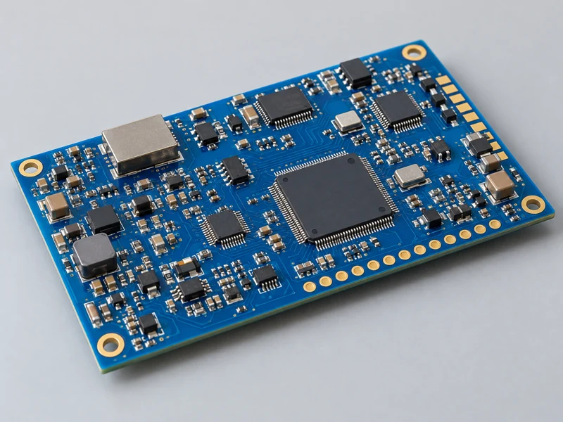
Compact SMT Prototypes
Evaluate densely populated designs with surface-mount ICs and passives. Review footprints, polarity, stencil requirements, and accessible test points.

BUILD • EVALUATE • REFINE
Turn a new PCB design into working engineering samples. MV Circuit coordinates boards, components, assembly, and agreed testing so your team can evaluate the next revision with a clear build record.
ENGINEERING SAMPLES
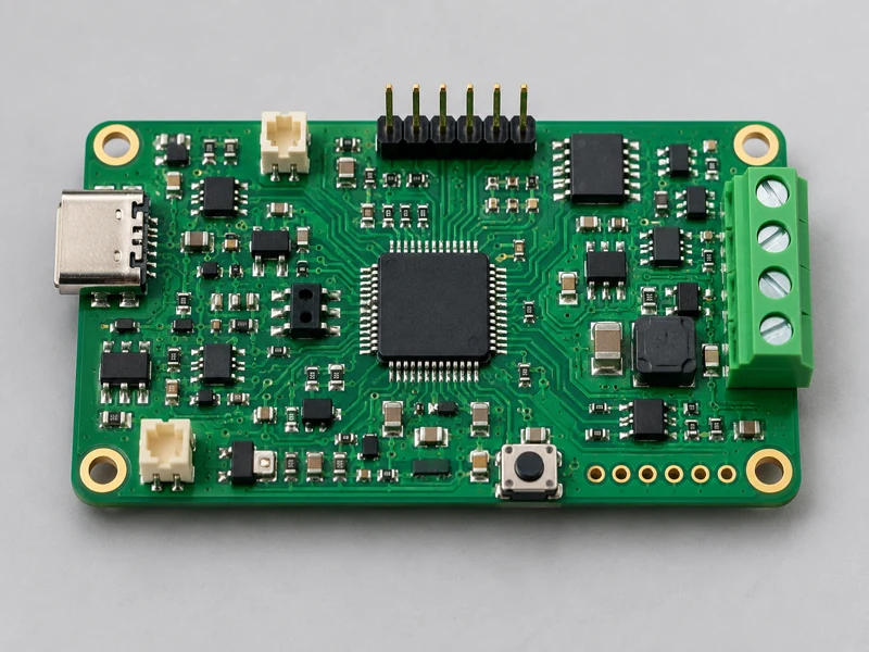
A prototype may be intended for first power-up, firmware development, mechanical fit, performance evaluation, or a small field trial. These goals need different quantities, configurations, and test preparation.
We review the PCB files, BOM, placement information, and assembly notes as one revision package. Optional parts, unusual connectors, programming access, and special handling are clarified before release.
An assembled prototype supports engineering validation. It does not automatically establish regulatory compliance, product reliability, or readiness for mass production; those require their own agreed validation plans.
PROTOTYPE CONSTRUCTIONS
Evaluate densely populated designs with surface-mount ICs and passives. Review footprints, polarity, stencil requirements, and accessible test points.
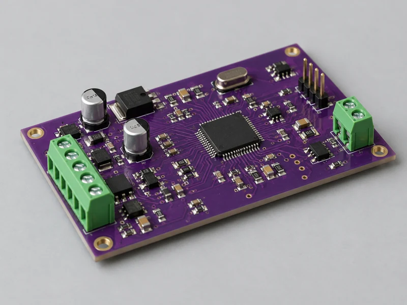
Combine fine electronics with leaded connectors, terminal blocks, and mechanically loaded parts. Coordinate soldering sequence and component clearance.
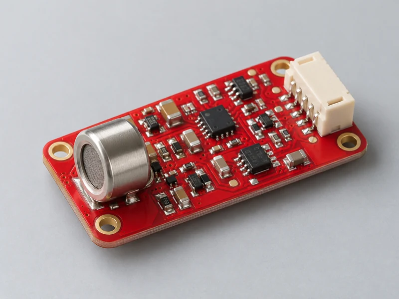
Build small sensing and interface boards for evaluation. Define analog, connector, shielding, and cleaning requirements in the assembly notes.
MATERIAL RESPONSIBILITY
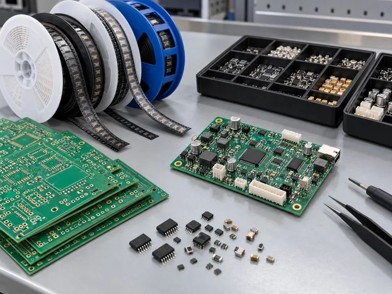
We coordinate bare-board fabrication and component procurement against the approved BOM. Resolve availability and purchasing questions before the build starts.
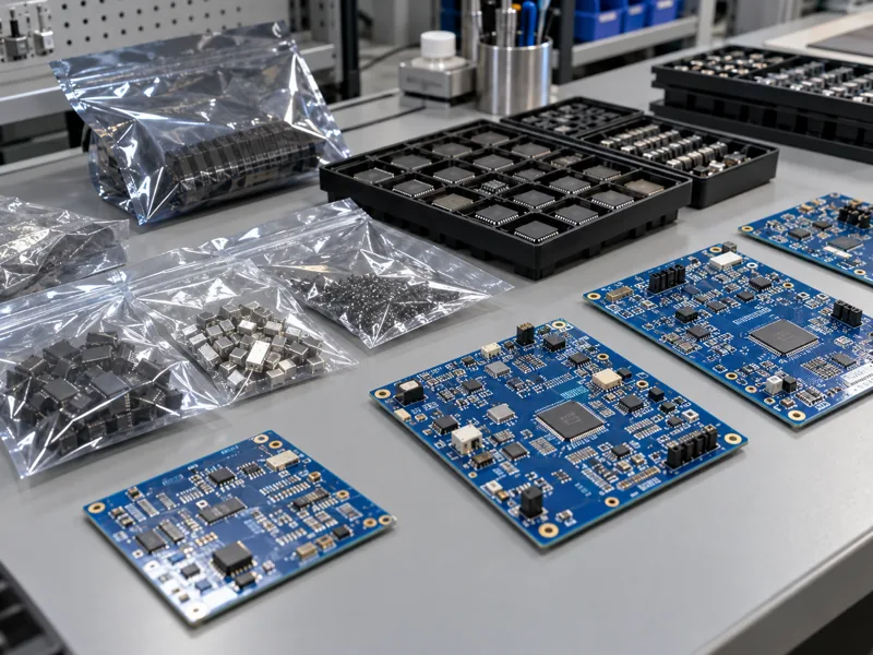
You supply the agreed boards or components. Confirm inventory, moisture-sensitive handling, setup allowances, and any special materials with the project team.
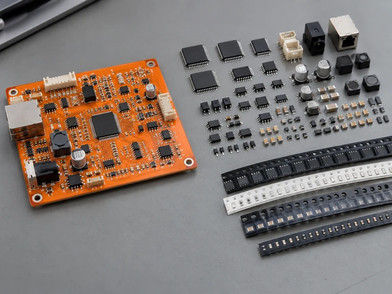
Combine customer-held devices with sourced standard parts. A clear responsibility list identifies each item, quantity, owner, and required delivery date.
FILES & CHANGE CONTROL
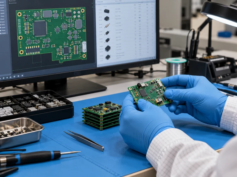
Match the fabrication files, BOM, placement file, assembly drawing, and firmware to the same release. Identify do-not-fit parts, polarity marks, connector orientation, and any manual operations.
For alternative configurations, provide variant-specific fitted reference designators and quantities. Approved component alternatives must match the electrical, mechanical, and firmware requirements of your design.
Keep an engineering change log between builds. If you revise the design after release, confirm the effect on purchased parts, tooling, completed work, and the identity of each delivered assembly.
PROJECT REVIEW
| Service Area | Prototype Scope | What to Define |
|---|---|---|
| Build quantities | Engineering samples and small-batch inquiries | Specify quantities per revision and configuration, including evaluation spares. |
| Assembly methods | SMT, through-hole and mixed technology | Review soldering sequence, carrier support, component access, and heat sensitivity. |
| PCB constructions | Rigid, flexible and rigid-flex projects by review | Match the actual board construction, panelization, tooling, and handling needs. |
| Package requirements | Passive parts, ICs, connectors and fine-pitch/BGA by review | Send package data, land patterns, inspection needs, and unusual mechanical constraints. |
| Sourcing model | Turnkey, consigned or partial turnkey | Confirm approved BOM, alternatives, material condition, and procurement responsibility. |
| First-article review | Agreed inspection or sample release checkpoint | Define the hold point, records required, and who can authorize continuation. |
| Programming and testing | Firmware loading and defined tests as agreed | Provide programming access, firmware version, safe operating limits, and measurable acceptance criteria. |
| Build records | Revision identity, variant and agreed release documentation | Specify labeling, traceability, deviations, and evidence needed for the next engineering stage. |
The quotation confirms the actual package limits, inspection scope, tooling, material responsibilities, and schedule. Request a dedicated review for unusual materials, sensitive components, or special acceptance requirements.
PROTOTYPE WORKFLOW
01
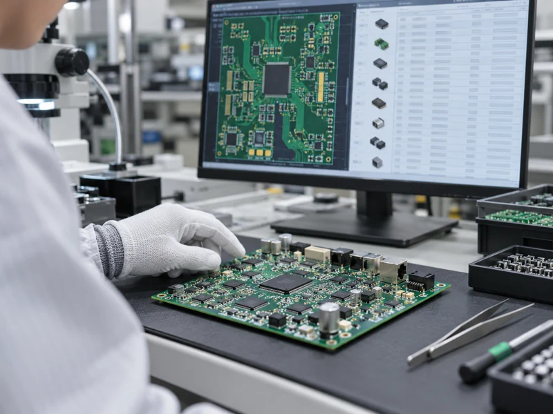
Confirm one release package, board revision, BOM, variants, and the purpose of the prototype.

02
Resolve stock, sourcing responsibility, approved substitutes, packaging, and setup allowances.

03
Prepare stencil and placement data, assemble the agreed first units, and apply any defined hold point.

04
Inspect placement, polarity, and soldering; document deviations before completing the remaining build.
05
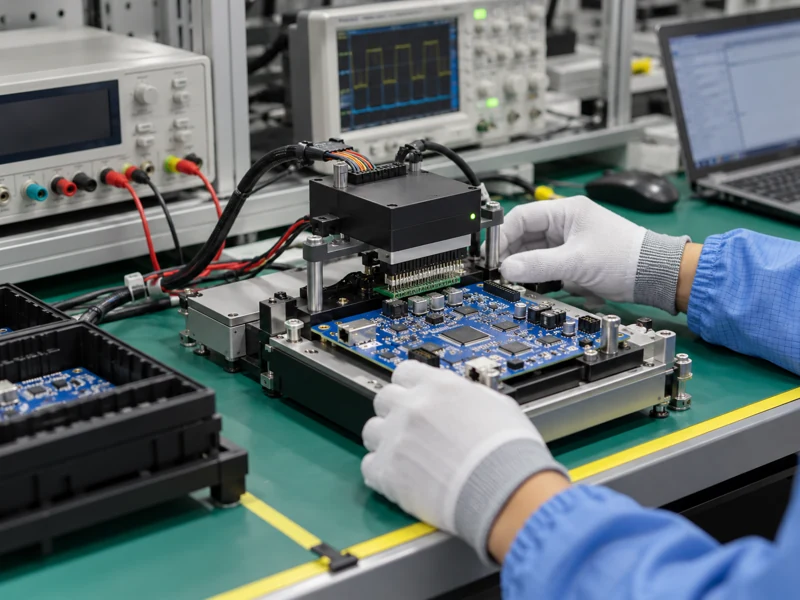
Load the approved firmware and run the agreed tests with defined power limits and acceptance criteria.
06
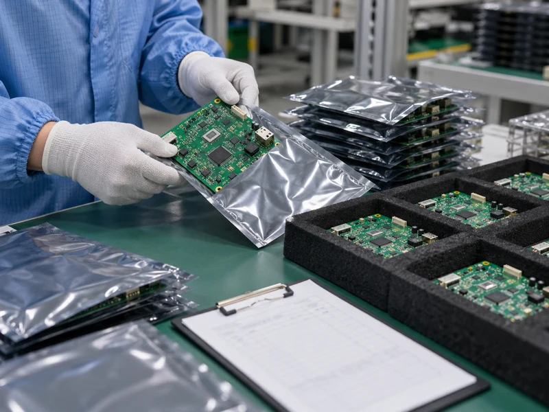
Deliver identified assemblies with agreed records so your team can evaluate findings and control the next revision.
INSPECTION & BRING-UP
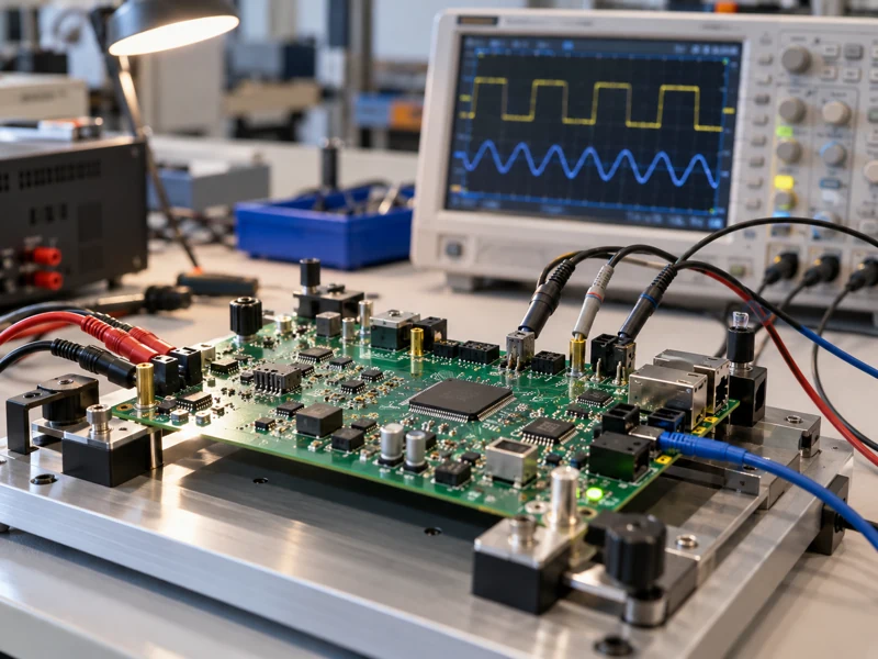
Visual inspection and AOI assess accessible workmanship features. Hidden joints may require an agreed X-ray inspection plan. Define any first-article evidence or approval checkpoint before assembly.
Powered testing needs a specific procedure: connections, current limits, firmware, operating sequence, and measurable pass/fail criteria. Identify test pads, programming headers, and any fixture requirements in advance.
Your engineering team uses the prototype to evaluate design performance. Keep test coverage, unresolved findings, and approved deviations visible so the next revision is based on documented results.
EVALUATION APPLICATIONS
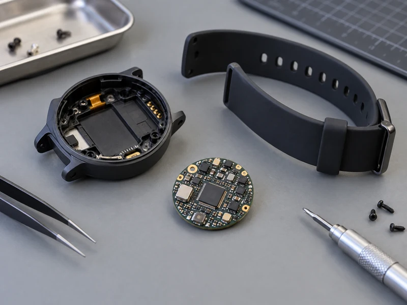
Evaluate compact sensor boards, battery interfaces, charging contacts, and fit inside wearable enclosures.
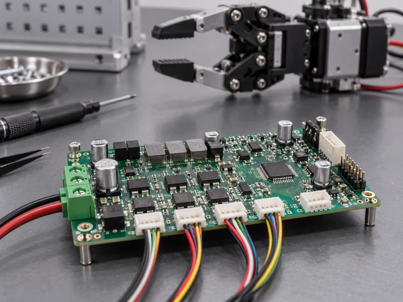
Check actuator interfaces, encoder feedback, motor control firmware, and integration with the mechanical system.
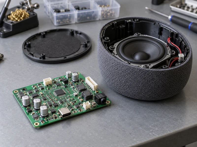
Build early audio and handheld product samples to review user interfaces, connector placement, and enclosure integration.
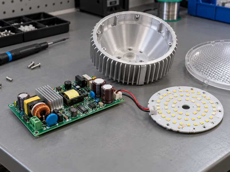
Evaluate driver operation, dimming interfaces, LED connections, and thermal behavior within the intended housing.
MV CIRCUIT
MV Circuit supports PCB fabrication, component sourcing, and assembly projects for customers across Europe, North America, and Asia. A coordinated project contact helps bring technical questions, material decisions, and assembly requirements together.
With over 18 years of PCBA manufacturing experience and no minimum quantity for new orders, we support small builds alongside repeat production. Sales and engineering support help clarify the approved release and project schedule.
When your evaluation leads to a design change, keep revisions, variants, and material decisions controlled. Our team can review the next build using the updated data and acceptance requirements.
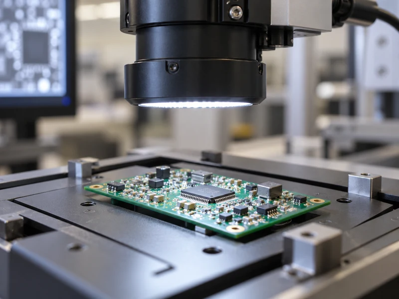
MANUFACTURING VIDEO
Explore the production overview from our official manufacturing channel. Ask how the assembly and inspection stages apply to your prototype requirements.
START YOUR PROTOTYPE
Send the fabrication files, BOM, pick-and-place data, and assembly drawing. Add quantities per variant, revision identifiers, sourcing responsibilities, delivery target, and your programming or test requirements.
Send Your Prototype Assembly Inquiry
Email: info@mv-circuit.com
COMMON QUESTIONS
Prototype PCB assembly is a small initial build used to evaluate a new or revised electronic design. It places and solders components onto the fabricated board so the engineering team can check operation, mechanical fit, firmware, and readiness for a later build. The validation plan should match the purpose of the prototype.
MV Circuit supports prototype inquiries without a minimum order quantity for new orders. Very small builds still require setup, a stencil where applicable, material preparation, and inspection. Ask for pricing at your intended quantities and identify any extra boards needed for destructive tests or separate teams.
Provide fabrication and drill files, BOM with manufacturer part numbers, pick-and-place data, and a matching assembly drawing. Include the revision, quantities, do-not-fit positions, polarity notes, firmware, and any test instructions. Clearly separate files for different design revisions.
Turnkey, consigned, and partial turnkey arrangements are available for review. For sourced parts, identify approved suppliers and alternatives. Customer-supplied materials need clear labels, packaging, quantities, and a responsibility list. Proposed substitutions require your approval before use.
Provide a separate assembly variant list or BOM for each configuration. Identify fitted and do-not-fit reference designators, quantity per variant, and any jumper or resistor options. Confirm the placement program, firmware, and labeling for each variant before the build is released.
Send the actual package, footprint, PCB construction, and inspection requirements for engineering review. BGA and fine-pitch assembly may require particular stencil, reflow, support, and X-ray provisions. Available limits are confirmed for the complete project rather than inferred from a package name.
Functional testing requires an agreed powered test specification. Supply the connections, safe power limits, firmware, sequence, and pass/fail criteria. Workmanship inspection and AOI do not prove circuit function. Confirm test access, fixture or cable requirements, coverage, and whether all units or selected samples will be tested.
The schedule depends on approved files, bare-board fabrication, component availability, assembly preparation, and test scope. Ask for a complete project schedule and identify long-lead parts early. A confirmed delivery date follows the agreed data and material release conditions.
Contact the project team immediately with a documented revision change. Work already completed, committed materials, tooling, or assembly programs may need review or replacement. Do not send a revised file with the same revision identifier; confirm which version applies to each board and assembly.
Close design and test findings, release a controlled revision, and confirm the final BOM, approved alternatives, panelization, firmware, test coverage, and acceptance plan. Prototype observations should inform the production build. Keep the quantity ramp and any remaining validation requirements explicit.
CUSTOMER FEEDBACK
“The team is highly responsive and always willing to provide expert advice.”Michael S. · USA
“The communication throughout the process is seamless. We highly recommend them for any PCB needs in the future.”Sarah L. · Germany
“Their quick turnaround times and dedication to ensuring we meet our deadlines make them an invaluable partner for us.”John D. · Italy
Existing feedback about MV Circuit’s overall PCB services. View the original feedback.